3.2 UHCA COMPONENT LAYOUT
3.2.1 Fuselage
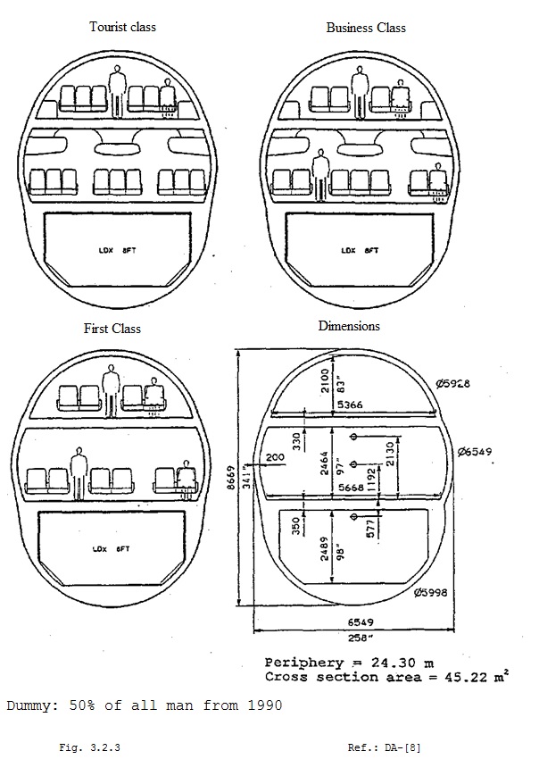
If a passenger capacity of more than 550 passengers is needed, a single deck configuration is of no interest; it would be too long. Alternatively, there are double width or double deck fuselages. To compare the aircraft with the B747-400 and not to encounter the problems of a double width fuselage, like structure, aerodynamics, safety and FAR admission, an ovoid cross-section was chosen for the fuselage.
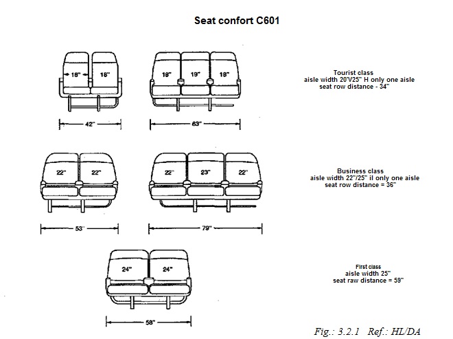
For the maximum length of the fuselage (80m) the width has to be evaluated. This is done by considering seat and class arrangement, passenger comfort, surface area and cargo compartment.
For the passenger accommodation the new B777 standard has been chosen. That standard takes up about 5% more deck area than the normal 3-class standard
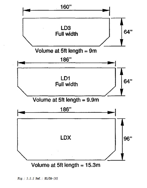
For cargo storage, a 32 in higher than the normal 8×8 ft LDl-container has been chosen to have enough cargo space in the ovoid. It is called LDX. To maintain trans-shipment it will also fit 8 ft pallets and 8×8 ft LCI-containers.
Fig.: 3.2.2 Ref.: HL/DA-[8]
From different ovoid cross-sections, the one with the minimum surface area and a large enough cargo compartment for LDX containers, was chosen.
Cross section C601
3.2.2 The wing
As described in 3.1.4 the current tendency towards a high wing aspect ratio was not followed. The main data of the 3-section trapeze wing are as follows (see also appendix III.2.2):
Wing
| Aspect ratio | A | 8.2 |
| Taper ratio | 0.235 | |
| Sweepback C/4 | * | 32° |
| Profile root thick. | 14% | |
| Profile tip thick. | 10% | |
| Span | m | 78.5 |
| Wing ref. area | m2 | 757.15 |
| Wing load | kg/m2 | 700 |
| M.A.C. | m | 11.5 |
The moderate aspect ratio proved to give an acceptable relation between wing mass and aerodynamic performance, even at that size.
To have a slightly higher lift at the same span and to reduce the induced drag, winglets have been added at the wing tips.
3.2.3 Horizontal stabiliser
The horizontal stabiliser was made for a volume factor of 0.8 The main data are as follows:
Table 3.2.3: Horizontal stabiliser
| Aspect ratio | A | 4.5 |
| Taper ratio | 0.4 | |
| Sweepback C/4 | «P | 35° |
| Relative thickness | 10% | |
| Root chord | m | 9.3 |
| Tip chord | m | 3.7 |
| Span | m | 29.5 |
| Area | m2 | 192 |
Because of the higher sweep and lower lift compared to the main wing, it was possible to take conventional profiles without drag increase by passing the critical mach number.
3.2.4 Vertical stabilizer
Like the elevator, the vertical tail is in charge of controllability and stability. Since the swept wing itself does not have to be stabilised around the vertical axis, the volume factor was exarninated for a surface, which was related to the fuselage geometry.
The aircraft has to be controllable with an engine failure. The calculations were made under the consideration of vertical fin area, thrust and lever arm (see appendix III.2.4.).
Table 3.2.4: Vertical stabiliser
| Root chord | m | 13 |
| Tip chord | m | 5 |
| Height | m | 13.5 |
| Area | m2 | 121.5 |
| Sweepback | <P | 40° |
The fin has 3 spars. The front spar is under tension and placed over the pressure cabin. The middle spar is on the bulkhead and the back spar is fixed on the trim screw jack connection spar. The two back spars are the boundary of the vertical stabiliser sparbox.
This lay-out is taken from the B747 to reduce the unused tail length.
3.2.5 Engine choice
The engine choice is mainly described in chapter 3.1.5. The sea level static thrust of the engine (GE90) is T0 = 342 kN to maintain the climb and start requirement.
The engines are located under the wing. This has positive effects on the aircraft balance, the bending moment relief of the wing and for the case of a failure of one engine.
Consistent with wing relief, it is of advantageous to put the engines close to the tip of the wing. For the failure of one engine, it is better to have them situated closer to the centre. That is the reason why the inner engines are close to the landing gears and the outer engines are slightly on the inside of the second wing bend.
3.2.6 Landing gears
The configuration of the main gear is 5 legs with 4 wheels each. The calculation of the Aircraft Classification Number (ACN) was evaluated with the ACNRI for rigid and the ACNFL program for flexible pavement (MBB DOC 9157-AN/901) . The results are compared with the ACN values of a B747-400 (see appendix III.2.6).
Table 3.2.6: ACN values for rigid and flexible pavements
| 747-400 | C601 | |
| ACN RA | 52 | 51 |
| ACN RB | 63 | 61 |
| ACN RC | 73 | 73 |
| ACN FA | 59 | 61 |
| ACN FB | 67 | 69 |
| ACN FC | 82 | 83 |
This undercarriage layout will provide the possibility of landing at the same airports as the 747-400, in consideration of the pavement.
32


